
Blog
Pressure management and pressure zones (PMA)
Every extra metre of pressure in a network raises both the risk of new bursts and the flow rate of existing leaks. Pressure management is the work of keeping the network at just the pressure it needs — no more, no less.
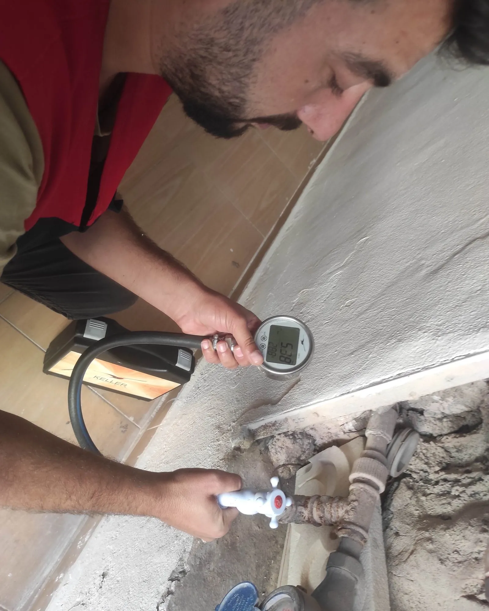
The link between pressure and leakage
The flow escaping any opening in a pressurised pipe — a hairline crack, a loosened joint, a corrosion hole — rises with the pressure in the main, and not linearly: leak flow is taken to vary with pressure raised to the power N1 (the FAVAD approach). N1 usually lies between 0.5 and 1.5 — near 0.5 for fixed-area holes and cracks in rigid pipe, near 1 for background leakage in flexible (plastic) pipe, higher where the opening widens with pressure. In a mixed network the practical value is around 1, so cutting the average pressure by 15% cuts the existing leak flow by roughly 15%.
Pressure has a second effect, on new bursts. High average pressure, and above all the pressure transients caused by pump and valve operations, accelerate fatigue in pipes and joints, so the break frequency rises. Lowering the pressure and holding it steady through the day drive the break rate permanently down. This is why pressure management is the first and fastest-returning step of a water-loss reduction programme.
What is a pressure managed area (PMA)?
A pressure managed area (PMA) is a part of the network similar in elevation and supply direction, bounded by closed valves and fed from a single point. The range of ground levels across its connections is kept narrow, so that one outlet pressure set at the inlet serves the whole area within acceptable limits.
A PMA often coincides with, or sits inside, a District Metered Area (DMA): the same closed boundary that makes flow countable also allows pressure to be managed from one inlet. Where the elevation range is wide, the area is split into several zones, each with its own target pressure.
The pressure reducing valve
A pressure reducing valve (PRV) is fitted at the zone inlet. It is a self-operated hydraulic control valve driven by a pilot circuit: it continuously adjusts how far it throttles so that the downstream pressure holds at a chosen target even as the inlet pressure and the flow change. Independent of make or model, the function is the same — bring the pressure of the water entering the zone down to what is needed and hold it there.
The valve is connected to a pressure data logger recording the inlet and outlet pressure and the zone flow. This record shows the setting is working and is the basis for the control modes described next.
Control modes
Fixed outlet: the valve holds a single downstream pressure whatever the inlet conditions. It is the simplest to commission; but because the target must suit the moment of highest daily demand, the zone stays at more pressure than it needs when demand falls.
Time-modulated: a controller changes the outlet target by defined time bands — lower at night when demand is low, higher at the morning and evening peaks. It needs little extra hardware; but because it follows the clock rather than real demand, the setting drifts if consumption departs from the expected pattern.
Flow-modulated: the outlet target varies continuously as a function of the measured flow through the valve. As demand falls the pressure falls, as it rises the pressure rises; the critical point is kept at just-adequate pressure at all times. It is the most effective mode for cutting leakage, and in return it needs a flow meter and a more capable controller.
How is the target pressure set?
The target is chosen not for the zone average but for its critical point: the connection at the highest elevation, or the farthest from the feed. At that point a minimum service pressure must be preserved even at the moment of highest demand — the lower limit the utility defines for the connection point.
The inlet target is worked back from it: the minimum service pressure at the critical point, plus the elevation difference to the inlet, plus the friction losses at peak flow, plus a safety margin. It is then verified with a pressure logger at the critical point over a full demand cycle, and the setting is trimmed to the lowest value recorded.
How is the gain measured?
The measure is a before-and-after comparison. The primary indicator is the zone's minimum night flow: when the pressure drops, it falls measurably within a few days. The secondary indicator is the count of bursts and failures over periods of similar length; as the pressure steadies, that count falls too.
For this the loggers at the inlet and the critical point are left in place. That the pressure reduction holds and the night flow does not climb again is monitored continuously; when a threshold is passed, the zone is surveyed again. The gain only lasts with this monitoring.
Validating the design
The pressure and flow records collected in the field — at the inlet, the critical point and intermediate nodes — are entered into a calibrated hydraulic model. The model checks that every node stays above the minimum pressure under all demand scenarios, assesses the valve size and the cavitation risk, tests the time- and flow-modulated profiles, and predicts the transients that operations would produce.
This validation shows the setting is safe not only in average conditions but at the extremes. LeakExpert runs field measurement, modelling and permanent monitoring as one programme, reporting each zone's target pressure, night flow and failure history together.
Also on the blog
Related articles.
How to tell if there is a water leak: 8 signs in a network
Signs of a hidden leak in a drinking-water network: rising night flow, pressure drop, a wi…
What is flow measurement, and how is it done in a network?
The purpose of network flow measurement, temporary measurement with a portable ultrasonic/…
What is acoustic water leak detection, and how is it done?
The steps of acoustic leak detection: survey with noise loggers, narrow down with a ground…
For your network
Let's measure the loss and pinpoint it.
In a short video call we can review the current situation and the method to apply.