
Blog
Locating a pipe route and depth
Before finding a leak, repairing it or mapping it, the first question is often: exactly where is the pipe, and how deep? Pipe locating is marking a buried main from the surface without digging.
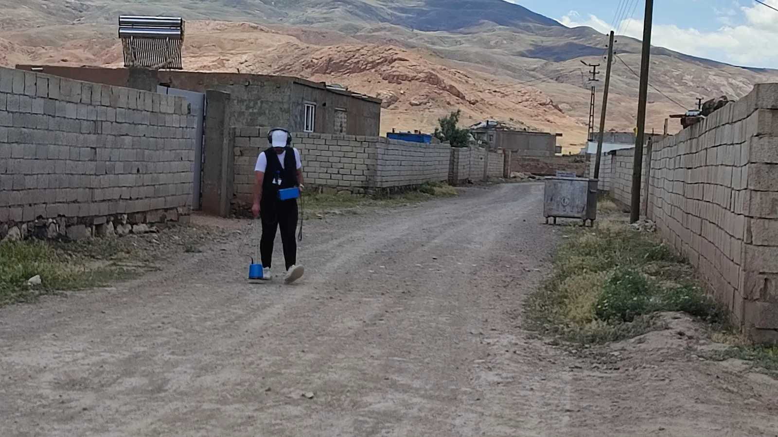
Why it is needed
Before any work on a buried drinking-water main, the first step is usually to establish where the pipe runs at the surface and roughly how deep it lies. Where the excavator bucket comes down for a repair dig; the exact position of the existing main when a new connection or valve chamber is planned; damage prevention when digging near other utilities such as power or gas — all of it depends on knowing the route.
Locating results also produce a permanent record. The marked route and spot depths are given coordinates and entered into a network mapping and GIS effort, so the survey need not be repeated from scratch at the next dig. The same geometry also confirms the pipe length and connection topology that feed a hydraulic model.
The scope is municipal and organised-industrial-zone distribution networks; what is being found is the route of street and arterial mains, without excavation.
Metal mains: the electromagnetic pipe locator
Conductive pipes — cast iron, ductile iron, steel — are traced with an electromagnetic pipe locator. The system has two parts: a transmitter that applies an alternating-current signal to the pipe, and a receiver that senses the magnetic field this signal creates from the surface.
The signal is applied in one of two ways. In a direct connection the transmitter lead is clamped straight onto an exposed point of the pipe — a valve spindle, a hydrant, a flange — which is the strongest and cleanest method. With an inductive clamp, a ring around the pipe induces the signal into it and no bare metal is needed for the connection. The transmitter can also be set on the ground, but then the signal is weaker and more likely to couple onto neighbouring conductors.
Walked along the route, the receiver traces the line of strongest signal as the pipe's plan position. The instrument also computes a depth estimate from the field geometry; that figure assumes the signal comes from a single, undistorted conductor.
Plastic (PE/PVC) mains
Polyethylene and PVC pipes are not conductive, so no electromagnetic signal can be applied to them directly. Tracing these mains needs a traceable element in or along the line.
The first method is a push probe or sonde: a flexible rod with a small transmitter at its tip is pushed into the pipe through a valve or fitting, and the receiver follows the position and depth of the probe tip from the surface. The second is tracer wire: a copper wire is buried parallel to the pipe as it is laid, and a transmitter is later connected to that wire so the main is traced as if it were metal. On new PE networks tracer wire is standard practice. Where neither is available, ground penetrating radar remains.
Ground penetrating radar (GPR)
GPR sends high-frequency radar pulses into the ground and records the reflections that return from the boundaries between different materials. As the antenna is pulled along a line over the surface, a buried pipe cross-section leaves a characteristic hyperbola on the radargram; the apex of that trace gives the pipe's horizontal position and the depth axis its approximate burial depth.
GPR is independent of material: metal, PE, PVC, concrete pipe and even a void are imaged on the same principle. Its performance, however, depends heavily on the ground. Dry sand and gravel give deep, clear results, while in wet clay the signal is absorbed quickly and little is visible below a few tens of centimetres. Interpretation gets harder with depth, in congested ground, and where the backfill is heterogeneous.
Marking and depth
The located route is made visible on site: the pipe centreline is sprayed onto the road surface with paint, or pegged and flagged in soft ground, with the centreline and station numbers written at set intervals.
Depth is measured not continuously but at selected points, and the instrument's depth estimate is noted there. The route and depth points are given coordinates with a hand-held GPS or a total station and turned into a sketch or a digital layer that can be imported into GIS. The survey thus becomes a permanent data product.
The limits of accuracy
No surface method reproduces a dig exactly. In electromagnetic tracing the biggest error source is other metal pipes running parallel to the target and dense buried services; they draw the signal onto themselves, shift the route line sideways and distort the depth estimate. A break in tracer wire, or a bad contact at a joint, can stop the trace at a point.
The depth figure is always an estimate; it rests on the pipe being single and straight and the field undistorted, and it usually departs somewhat from the true depth. GPR interpretation depends on the operator and the ground; a hyperbola is not always the pipe being sought.
For this reason, before a critical excavation, a small hand-dug trial pit is opened over the marked point to verify the pipe's real position and depth by eye. The locating work and the interpretation of its results can be planned over a remote or video call; once the network sketch, material data and access points are shared, the method and the marking plan are set together.
Also on the blog
Related articles.
How to tell if there is a water leak: 8 signs in a network
Signs of a hidden leak in a drinking-water network: rising night flow, pressure drop, a wi…
What is flow measurement, and how is it done in a network?
The purpose of network flow measurement, temporary measurement with a portable ultrasonic/…
Pressure management and pressure zones (PMA)
How high and fluctuating pressure drives leaks and bursts, setting up a pressure managed a…
For your network
Let's measure the loss and pinpoint it.
In a short video call we can review the current situation and the method to apply.